
Ads by Google


1. Applications and characteristics
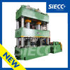
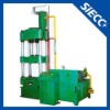
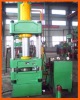
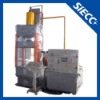
Four-column Hydraulic Press adopts optimized design, the frame is entirely welded with steel plates, and treated to relive stress by tempering for high precision. This product is widely applied in various forming technology, including the processing and forming of various plastic material, such as extrusion, bending, ruffled, deep drawing, etc.
Cartridge valve equipped for hydraulic control system, reliable, durable and less hydraulic shock, with shorter connection pipeline and fewer release points.
Independent electrical control, reliable and convenient for maintenance. Centralized button control system, with adjustment, semi-auto operation modes at the operator’s choice.
Semi-auto has two tech: set-stroke single and set-pressure single, with pressure hold and time delay functions. The operating force, low-speed movement and travel range can be adjusted subject to technological requirements.
2. The main technical parameters
No. | Description | Unit | Specification | |
1 | Rated pressure | KN | 6300 | |
2 | Max. pressure of liquid | Mpa | 25 | |
3 | Return force | KN | 1240 | |
4 | Daylight Opening height | mm | 1500 | |
5 | Stroke of slide | mm | 900 | |
6 | Knock-out pressure | KN | 1000 | |
7 | Stroke of knock-out | mm | 350 | |
8 | Speed of slide | Descent | mm/s | 100 |
pressing | mm/s | 12 | ||
Return | mm/s | 60 | ||
9 | Speed of ejection cylinder | Knock-out | mm/s | 40 |
Return | mm/s | 120 | ||
10 | Size of worktable | L-R | mm | 1500 |
F-B | mm | 1500 | ||
11 | Overall dimensions of machine | L-R | mm | 4200 |
F-B | mm | 2500 | ||
Height above ground | mm | 5500 | ||
12 | Motor power | KW | 2*22 | |
3. Structure Overview
This machine consists of host machine, hydraulic system, electrical system, etc. Through the piping and electrical device connected to form a whole.
3.1.Host machine
The host machine is organized by top rail, slide, working-table, workbench, guide rail, uprights, locknuts and adjusting nut.etc. Rely on four uprights as the main frame, The top rail and work-table by locknuts fixed on both ends, the slide installed in the middle of them. The precision of the machine can be adjusted through adjusting the locknuts and adjusting nuts that tightened on the top rail. Slide and master cylinder piston rod through the connecting flange connection, rely on the uprights up and down.
There are T-slot on the slide and working-table, so that the tools can be equipped convenience.
3.2. Master cylinder
The master cylinder body can be fixed in the beam by cylinder shoulder and locknut. Slide and master cylinder piston rod through the connecting flange connection, Piston head material is cast iron, used for guiding.
Piston head cylindrical place installed direction opposite rings, O-ring installed in its inside. Make the cylinder form two cavities. Cylinder guide sleeve also installed seal ring, rely on the flange to lock, ensure the inferior cavity sealing.
The cylinder body and piston rod are made of high quality material, professional manufacture. The piston rod surface after quenching treatment, the hardness of the guide section about HRC45.
3.3. Cushion cylinder
The ejection cylinder installed in working-table center hole, fixed by the flange, the structure is similar with master cylinder.
3.4. Electrical work station
The work station can be moved within limits, buttons and time relay installed on the pane.
3.5. Hydraulic system
Hydraulic system is the device of the generation and distribution of the working fluid. The device consists of fuel tank, cartridge valve integrated system, motor and pump.
The various components of the actuating unit described as below:
3.5.1. The fuel tank
Including the fuel tank, air filter, level gauge etc. tank uses the steel plate welding, cooling capacity is good, the air filter doubles as the oil inlet.
3.5.2. Hydraulic power system
Including motor and Axial piston pump. Coupling connecting the motor and the pump, composition motor oil pump group. The pump variable can automatically change according to the working pressure.
The machine use 80YCY14-1B axial piston pump, use Y-180L-4 22KW motor as the drive element. The machine use the working pressure is 25Mpa.
3.5.3. Hydraulic control system
Cartridge valve equipped for hydraulic control system, reliable, durable and less hydraulic shock, shorter connection pipeline and fewer release points.
3.6. Stroke limit device
3.6.1.Slide stroke limit device: It is located on the right side of the machine, including stroke angle iron, induction block and proximity switches. Adjust position of the proximity switch can adjust the slide running position.
3.6.2. Ejection cylinder stroke limit device: Adjust position of the proximity switch can adjust the ejection cylinder running position.
3.6.3. The pressure sender adopt electric contact pressure gauge SP.
SP----The upper cavity of the master cylinder pressure sender switch.
3.7. The electrical control system
Electrical system is according to the technological requirements of the hydraulic press, with Adjustment and Semi-automatic two process.
The electrical control including, the main circuit, the control circuit, indicator circuit, the solenoid circuit and the protection circuit, etc.
3.7.1. The main circuit
Three-phase 50HZ AC power, through the automatic air switch on and breaking the total power.
The main circuit including, automatic air switch, Insurance, Star delta starter, thermal relay and motor.
The motor parameter as below:
Y2-180L-4 22KW ~380V 50HZ 1470r/min
3.7.2. The control circuit
The control supply voltage is AC220V, Selected switch SA have adjustment and semi-automatic two ways of working.
3.7.2.1. Adjustment: Selected switch SA in “Adjustment” position, start motor, press the “Suppress” or “Return” button, can get the corresponding action. Release the button, the machine immediately stop action.
3.7.2.2. Semi-automatic: Selected switch SA in “Semi-automatic” position, start motor, press the “Suppress A+B” button, the machine complete a cycles.
Choose “Ejection” button, Slide quick decline→Slide run into the limit switch SQ2, Slide slow down→The upper die contacts with the lower die, the upper cavity pressure will lift, when the pressure achieve the stress signaling SP1, the slide stop motion, holding pressure time relay to start work→The time arrive, the slide return trip to upper limit SQ1→The ejection cylinder knock out to upper limit SQ4→The ejection cylinder automatically return to the lower limit SQ5→The machine complete a cycles
Choose “Unroofed” button, the ejection cylinder no action. The rest of the action is same with “Have ejection”.
Choose “Tensile” button, The ejection cylinder is located in the upper limit SQ4→Slide quick decline→Slide run into the limit switch SQ2, Slide slow down, the ejection floating down→The upper die contacts with the lower die, the upper cavity pressure will lift, when the pressure achieve the stress signaling SP1, the slide stop motion, holding pressure time relay to start work→The time arrive, the slide return trip to upper limit SQ1 →The ejection cylinder knock out to the upper limit SQ4→The machine complete a cycles.
3.7.3. The solenoid circuit
This machine has nine solenoid valves, the working voltage is DC24V.
3.7.4. The protection circuit
3.7.4.1. The motor control loop is equipped with insurance and thermal relay for short circuit and overload protection.
3.7.4.2. In the control circuit is equipped with fuse for short circuit protection.
3.7.4.3. The operating table is equipped with “Stop” button, can achieve the emergency shutdown.
3.7.4.4. The machine installed ground wire.
4. Maintenance and safety operation procedures
4.1. Maintenance
4.1.1.The machine uses the L-HM46 anti-wear hydraulic oil <GB11118.1-1994>, operating temperature is 15°C~65°C.
4.1.2. Oil should be strictly filtered to tank, the oil tank quantity not less than the level gauge central level.
4.1.3. The new machine use a week later, check on the degree of oil contamination, the solid pollution level is not higher than 19/16.
Use three months later, then conduct a check. Once every six months to replace oil.
4.1.4. Machine under the nominal pressure of 5000KN, the maximum eccentricity not more than 25mm.
4.1.5. Every half an year check pressure gauge, every year clean the hydraulic station.
4.2. Safety procedures
4.2.1. Do not understand the structure of the machine and safety procedures are not allowed to start the machine.
4.2.2. In the machine process, mustn’t repair and adjust the mold.
4.2.3. When the machine found a serious oil spills or other abnormalities (such as the action is not reliable, noise, vibration, shock, etc.), should packing analyze the reason, try to eliminate failure.
4.2.4. Shall not be overloaded and exceeding the maximum eccentricity.
4.2.5. Wiring resistance shall not be greater than 0.1Ω.
5. Spare parts and Technical data
5.1. Provides a set of O-rings and combination washer of the pipe joints;
5.2. Provides foundation bolts, nuts and a set of special tools;
5.3. Provides Operating instruction, Packing list and Certificate of conformity.