Ads by Google


COUPLERS
Directional coupler is commonly used for sampling microwave signals in specified flows. In the absence of the load, directional coupler is usually a 4-port network. Generally adopting parallel coupling lines, the length of coupling zone is an integral multiple of one-fourth wavelength. Coupler’s direct output is not adjacent structurally to the coupling port, with discrepancy of output phase of 90 degrees or 180 degrees. The remaining port is called isolation port, which does not export any energy theoretically.
Parametric description:
Coupling: the ratio of output power of coupling port to input power of main line when remaining ports matched with load Coupling loss: output power reduction caused by a coupling port, equal to theoretical value of insertion loss of main-line The relation between min. theoretical value of the insertion loss of main-line and coupling degree is as follows: Coupled degrees: 3dB 5dB 7dB 10dB 15dB 20dB Theoretical loss of main line: 3.0 dB 1.65dB 0.97dB 0.46dB 0.14dB 0.04dB Main line loss: changes of power obtained by load due to the coupling in transmission system when matching load is connected to each port excluding main line, including two aspects of energy coupling loss and energy dissipation loss
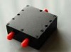
Directional coupler